You can attach additional
hardware to the ports of the microprocessor.
The following statements will become available :
I2CSEND and I2CRECEIVE and other I2C related statements.
LCD, LCDHEX, DISPLAY and other related LCD statements.
1 WIRE bus explanation.
More about connecting a LCD display.
Hardware related commands
The uP must be connected to a crystal. The frequency of the crystal can
range from 0 to 24 Mhz for most chips. The frequency is divided by 12
internally.
So with a 12 Mhz crystal
the processor is clocked with 1 Mhz.
Because almost each instruction takes, 1 clock cycle to execute the processor
can handle 1 MIPS.
When RS-232 statements
such as INKEY, PRINT and INPUT are used, TIMER1 is connected to the system
clock.
So TIMER1 cant be used for other purposes such as ON TIMER1 anymore.
When no RS-232 related statements are used you can use TIMER1.
The Baud rate is generated
by dividing the system clock.
When a crystal of 11.0592 Mhz is used, the Baud rate can be generated
very accurately.
Other crystals can
be used too but the generated baud rate will never be exactly
2400 or 4800 baud and higher baud rates are almost impossible.
The exact baud rate is shown in the report file.
Clock
The clock frequency is the system frequency divided by 12.
With a 12 Mhz crystal this means that every microsecond the register is
incremented.
Timers and Counters
The 8051 has two 16-bit timers named TIMER0 and TIMER1.
Below the internal representation of timer0 is shown.
TIMER0 and TIMER1 are almost identical so you can read TIMER1 for TIMER0.
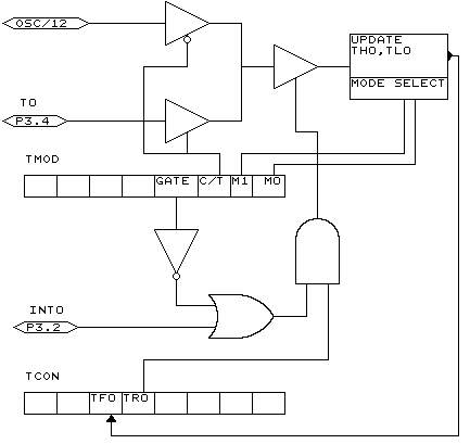
Each counter register has two SFRs associated with it.
For TIMER0 the SFRs are TL0 and TH0.
TL0 is the lowest byte of TIMER0 and TH0 is the highest byte of TIMER0.
These two registers make the timers 16-bit wide.
The timer can operate
as a timer or as a counter.
A timer uses the system clock divided by 12 as the source of its input
pulses.
So it increments periodical.
A counter uses
external pulses to increment its count.
The external pulses are received at alternative pin P3.4 for TIMER0 and
P3.5 for TIMER1.
The timer/counter can be controlled by the run-bit TR0.
You can stop a timer/counter
with the statement STOP TIMER0/COUNTER0.
You can start a timer/counter with the statement START
TIMER0/TIMER1.
The timer/counter
can also be controlled with the alternative pin P3.2.
This pin is labeled for its alternative INT0-input but it can be used
to control the timer.
When GATE is reset the timer/counter is enabled.
When GATE is set the timer/counter is enabled if INT0 is active(low).
(provided that the timer is started)
The timer/counter can operate in four modes:
� mode 0 : 13-bit counter.
An interrupt is generated when the counter overflows. So it takes 8192 pulses to generate the next interrupt.
� mode 1 : 16-bit
counter.
Mode 1 is similar to mode 0. It implements a 16-bit counter.
It takes 65536 input pulses to generate the next interrupt.
� mode 2 : 8-bit auto reload.
TL0 serves as an 8-bit timer/counter.
When the timer/counter overflows the number stored in TH0 is copied into
TL0 and the count continues.
An interrupt is generated each time the counter overflows and a reload
is performed.
� mode 3 : TIMER1 is inactive and holds its count. (TIMER1).
For TIMER0 in timer mode two 8-bit timers are available and in counter
mode one 8-bit timer is available. See a datasheet for more details.
The timer/counter
can be configured with the CONFIG statement.
CONFIG TIMER0= COUNTER/TIMER, GATE=INTERNAL/EXTERNAL, MODE=0-3
The first argument is the timer/counter you want to configure, TIMER0
in this case.
GATE specifies if external timer control with the INT0 pin is enabled.
MODE specifies the timer/counter mode (0-3).
So CONFIG TIMER0 = COUNTER, GATE = INTERNAL, MODE=2 will configure TIMER0 as a COUNTER with not external gatecontrol , in mode 2 (auto reload)
When the timer/counter is configured the timer/counter is stopped so you must start it afterwards with the START TIMER0 statement.
The ON TIMERx statement can be used to respond to a timer/counter interrupt when the timer overflows.
When the timer/counter
is used in mode 2 (auto reload) the reload value can be specified with
the LOAD TIMERx, value statement.
Because it is an 8-bit register a maximum time of 255 uS can be achieved.
So for a period of 10 uS you must supply a value of (256-10) is 246. To make things easier you can assign the value directly : LOAD TIMERx , 250 will internally be transformed into 256-250=6.
This saves you the trouble of calculating the correct value.
The COUNTER0 and COUNTER1
variables hold the values of timer/counter 0 and 1.
You can also set the timer/counter contents with the COUNTER0 = value
statement.
Please note that you
with the LOAD statement, you can only load a byte value into the timer/counter.
Because the statement is meant for timer/counter mode 2.
Also note that you can assign a value to the timer/counter with the COUNTER0/COUNTER1 variables. You can not use the TIMER0/TIMER1 in it's place but it does the same thing : assigning/retrieving the timer/counter.
Port 3 is a unique
port because it has alternative functions.
That is you can use it as a port like P3.1 = 1 or SET P3.1 or you can
make use of the double function of this port.
| Port | Alternative function |
| P3.0 | RxD receive data for RS-232 |
| P3.1 | TxD transmit data for RS-232 |
| P3.2 | INT0 interrupt 0 input/timer 0 gate control |
| P3.3 | INT1 interrupt 1 input/timer 1 gate control |
| P3.4 | T0 timer 0 input or counter input |
| P3.5 | T1 timer 1 input or counter input |
| P3.5 | - |
| P3.7 | - |
When you make use
of the PRINT, INPUT and other RS-232 related statements
P3.0 and P3.1 are used for the RS-232 interface.
When you make use
of the INT0/INT1 interrupts, you must connect an interrupt source to the
corresponding pins. A switch for example.
The INTx interrupt can occur on the falling edge of a signal or when the
signal is low.
Use the following statements to specify the trigger:
SET TCON.0 Falling edge generates interrupt for INT0.
RESET TCON.0 Low signal generates interrupt for INT0.
SET TCON.2 Falling edge generates interrupt for INT1.
RESET TCON.2 Low signal generates interrupt for INT1.
When TCON.x is RESET the interrupts keep on occurring while the input
is low.r When TCON.x is SET the interrupt only occurs on the falling edge.
To test if a hardware
interrupt is generated you can test the TCON.1 and TCON.3 flags.
These flags are set by hardware when an external interrupt edge is detected.
They are reset by the RETURN statement of the interrupt service routine
or subroutine.
TCON.1 must be tested for INT0 and TCON.3 must be tested for INT1.
Some uPs have an additional timer named TIMER2. It depends on the used chip which features TIMER2 has.
Ports
& Power Up
Port 1 is an 8-bit bi-directional I/O port. Port pins P1.2 to P1.7
provide internal pull-ups.
P1.0 and P1.1 requires external pull-ups. P1.0 and P1.1 also serve as
the positive
input(AIN0) and the negative input(AIN1), respectively, of the on-chip
precision
analog comparator.
The port 1 output
buffers can sink 20 mA and can drive LED displays directly.
When 1s are written to Port 1 pins, they can be used as inputs.
When pins P1.2 to P1.7 are used as inputs and are externally pulled low,
they will source current because of the internal pullups.
Port 3 pins
P3.0 to P3.5, P3.7 are seven bi-directional I/O pins with internal pull-ups.
P3.6 is hard wired as an input to the output of the on-chip comparator
and is not
accessible as a general purpose I/O pin.
The port3 output buffers
can sink 20 mA.
When 1s are written to Port 3 pins they are pulled high by the internal
pullups and can be used as inputs.
Port 3 pins that are externally being pulled low will source current because
of the pullups.
Port 3 also serves the functions of various special features of the AT89C2051 as listed below.
| Port | Alternative function |
| P3.0 | RxD receive data for RS-232 |
| P3.1 | TxD transmit data for RS-232 |
| P3.2 | INT0 interrupt 0 input/timer 0 gate control |
| P3.3 | INT1 interrupt 1 input/timer 1 gate control |
| P3.4 | T0 timer 0 input or counter input |
| P3.5 | T1 timer 1 input or counter input |
| P3.5 | - |
| P3.7 | - |
Writing to a Port
P1 = 255 will write the value 255 to the port 1, setting all the pins
to 1
so all pins can be used as inputs.
P1 = 0 will write the value 0 to port 1, setting al pins to zero.
Reading from a
Port
byte = P1 will read the value from port 1 and will assign the value to
variable byte.
Setting individual pins of a Port
You can also set individual pins of the ports in BASCOM.
SET P1.0 will set pin P1.0 high.
P1.0 = 1 will also set pin P1.0 high.
RESET P1.0 will set
pin P1.0 low.
P1.0 = 0 will also set pin P1.0 low.
At power up both ports are high and can be used an inputs.
Individual bits can be set to use a port both as input/output.
For example : P1 = &B00001111 , will set a value of 15 to port 1.
P1.0 to P1.3 can be used as inputs because they are set high.
How to interface the port pins
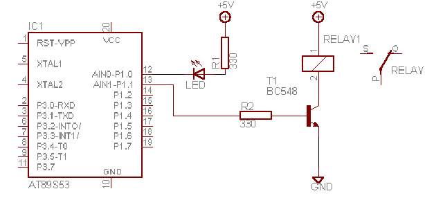
The schematic above shows how to connect a LED and a relay as an output.