Cart is empty.
Item Quantity Price Total: $0

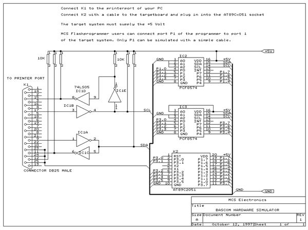
AN #10 - BASCOM-LT and BASCOM-8051 Hardware simulation
This application note shows how to emulate PORT 1 and 3 so you can test the various port statements from within the BASCOM IDE.
The schematic is almost the same as for the MCS Flashprogrammer.
2 PCF 8574 I/O extenders are used which are controlled by an I2C interface.
Users of the MCS Flashprogrammer can use the programmer to simulate PORT 1 (port 3 not supported).
You can make a cable which connects P1 of the flashprogrammer (with a piggy-back) to the target system(the AT89C2051 socket).
Take care not to insert a chip into the programmer when used as a simulator!
A simple program demonstrates the simulator :
Connect 8 LED via 330 ohm resistors to P1. Simulate the program and see what is happening.
In this application notes was used a dontronics DT003 power-board as a basis, a DT203 led/button board for the leds and a dontronics prototype board to connect P1 of the flashprogrammer to the data lines of the SIMM-bus.
For info on these boards http://www.dontronics.com
Dim a As Byte
P1 = 1
For a = 1 to 8
Rotate P1 , Left
Next
For a = 1 to 8
Rotate P1 , Right
Next
End