
Cart is empty.
Item Quantity Price Total: $0

AN #125 - How to set up zero crossing software to trigger a Triac
This AN was submitted by Mike Crean
Here is some additional info from Mike. He sent this after the first circuit was published.Ā
If anyone is trying to use the zero
crossing detector in AN125 there are corrections.
The 10k resistor from pin 1
of the 4069 hex. Inverter should NOT be pulled LOW
It should be pulled HIGH
(5V+). The pulse width on pin 4 should be less than 1ms.
The pull up resistor
on the collector of the BC548 should be 1K NOT 1K5.
If anyone is using a
sensitive gate TRIAC remember to use a bias resistor (10k) on
the gate to
neutral or timing cap line side. This will prevent erratic triggering
by
external electrical noise.
The 2nd. zero crossing circuit in AN125
should be used for more stable operation
of the TRIAC.
It also shows how to use Timer0, Urxc ISR and ADCs from theĀ AT90S8535.
Here are two methods to derive the zero crossing from the mains.
DANGER - WARNING
High voltages are present when equipment is connected to a mains supply.
Some Authorities may only allow suitably qualified & licensed persons to connect any such equipment to a high voltage supply.
Take CAUTION. Avoid electric SHOCK
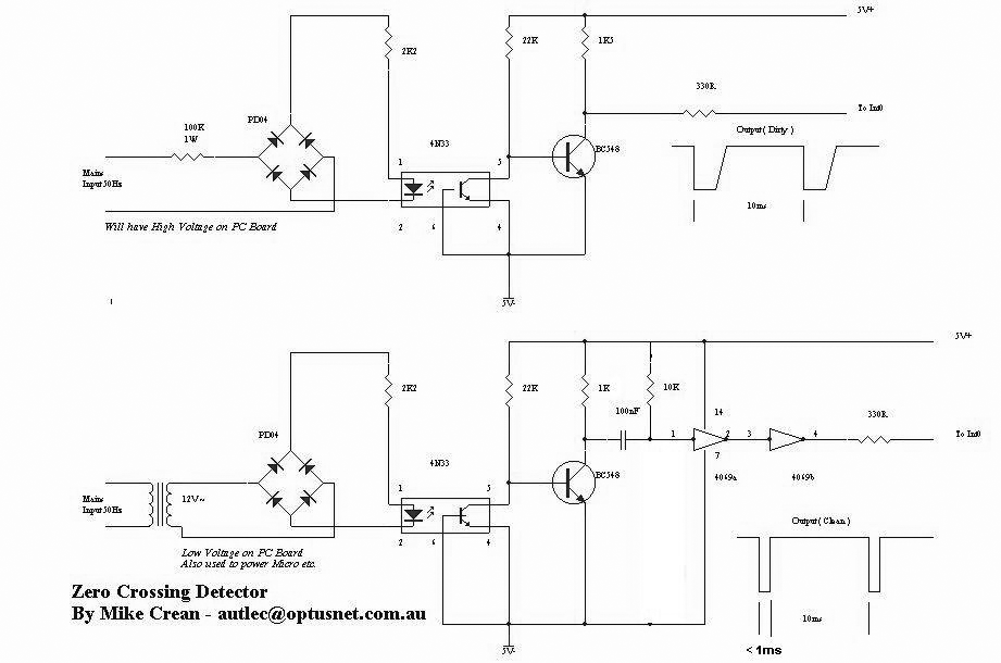
The pulse time will depend on the mains frequency used in your country.