Cart is empty.
Item Quantity Price Total: $0

AN #133 - 90S2313 Alarm Clock
This application note was submitted by Nick Baroni.
This Ap Note describes a time clock switch with individually setable on and off times. It is based on a AT90LS2313 and a surplus nine digit common cathode 7 segment LED display such as those found in older calculators
Design notes:
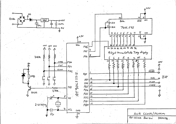
The hardware is described in figure 1. The heart of the unit is a AT90LS2313 run at 2.4576 MHz. A 74HC595 shift register sinks the cathode current from the display. The LED display has tiny (~3mm high) digits and the segment current is about 1.8 mA, set by the 1.8k anode resistors. Even with all digits in a segment on, the resulting 12mA is within the capabilities of the 595.
The cathode of digit 1 is connected to PortD.6 of the 2313. The 595's shift register and latch clocks are tied together. This has the effect of delaying the output and the data input by one clock cycle. Advantage of this is taken in the code.
Three push buttons provide mode and time setting control. The mode switch cycles the control mode between 'run', 'set', 'on' and 'off'.
In the run mode, the slow and fast buttons either turn on or off the load. In the other modes, they increment the time settings. I elected to provide external pull ups rather than enable the internal ones.
An accuracy of 1 second per day implies a frequency accuracy of 1/86400 or 11.6 ppm. Most common CPU crystals are not this accurate and a small trimmer is used on Xtal1 to tune the frequency.
The display is multiplexed. This means that only one of the nine digits is turned on at any time. In order to stop the display flickering, it is important to update each digit quickly enough to allow persistence of vision to make the observer think that all digits are on continuously.
The timer0 overflow interrupt is used to do the display update and count off the time. The crystal used needs to be able to be divided down to exactly one second other wise the clock won't keep accurate time.
The 2457600 Hz clock is divided by 64 to 38400 Hz. Timer 0 is preloaded with 160 every interrupt. This makes timer0 divide by 96 (160 + 96 = 256). The resultant interrupt rate is then 400 Hz.
When the program isn't updating the display, it reads and reacts to the buttons and calculates the display contents.
The following compiler settings were used for this project.
Stacksize=56
Framesize=32
Sstack=8
Figure 1