Cart is empty.
Item Quantity Price Total: $0

AN #119 - RC LapTimer
DESCRIPTION
The following application note is a description of a method I used to record number of laps and time to complete laps for radio controlled cars.
This application can only be used for one car at a time. The ability to monitor racing performance greatly enhances the productivity of training sessions by providing important performance info and an incentive to improve.
OPERATION
The basic operation of the lap timer is simple. The unit is placed in a convenient area next to the racetrack with the beam sensor facing the track.On the other side of the track is where a laser module is located with the beam crossing the track terminating on the beam sensor.
When the unit is first powered up, a graphic bitmap is displayed for five seconds.
Next the unit will ask, "SELECT LAP MARKER" number. When the stop/review button is held, the number will increment. The user will release the button when the desired lap to be marked is displayed.
When the counter reaches the selected lap during a session, a led will turn on. If a lap mark is needed, the user will select 0. After five seconds the unit will look for the beam.
The display will read, "ALIGN LASER" if the beam is not present at the sensor.

After the beam is detected the display will read, " LASER ALIGNED".

The unit will wait for two seconds and display a progress bar. The unit will check again for laser alignment. Once a steady beam has been detected, the unit will display, "START WHEN READY".

The unit is now waiting for the beam to be broken from the first pass. The first pass will start the timing/counting process, and the unit will display, "LAP TIME" at the top.
When each lap is completed, the unit will display the lap number and the time it took to complete.
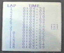
There is a three second delay after the beam is broken before another detection will be recorded. This allows the RC car to pass completely through the beam without false detection. The delay can be changed in software if laps are shorter then five seconds. A clock bitmap will scroll down the side during the session. This provides a visual indication that the timer is working. The unit will also save each lap (up to 124) in eeprom memory and print to the lap info to the serial port. After fifteen laps, the display will clear and start with lap sixteen at the top and continue to display additional laps as they are completed. When the session is finished a push of the stop/review button will stop the timer/counter process. The unit will clear the screen and display, "PUSH TO REVIEW".
When the button is pushed again, the unit will begin to display the lap/time information. If there are more then fifteen laps, successive button activation will display additional laps fifteen at a time. The last lap will be indicated by the word "END" printed after the lap time. When the stop/review button is pressed again, the following information will be displayed and printed to the serial port of the unit: TOTAL RACE TIME, NUMBER OF LAPS, AVERAGE TIME OF LAPS, AND QUICKEST LAP TIME.
Additional button activations will continue to review the session info from the beginning. The unit must be re-set to start another session. If the laser is not detected after the three-second delay, the unit will display "LASER FAULT". The session will end and must be reset. Any laps that were complete will be remembered.
SPECIAL NOTES
I recommend a laser module that is 670nm in wavelength. A typical inferred diode has a band with that is 620nm on the low-end. A printer or laptop can be used to capture the lap info that is printed to the unit's serial port. The schematic shows a battery connected to the display. This battery is used to provide the negative voltage for the contrast. The builder should pay close attention to the recommended method of connection for the display that is used. I would recommend a display that has the negative voltage generator built-in to the display.