Cart is empty.
Item Quantity Price Total: $0

AN #144 - CodeLock AVR
CodeLockAVR - electronic combination lock with AT90S2313
By Rudi Slejkovec
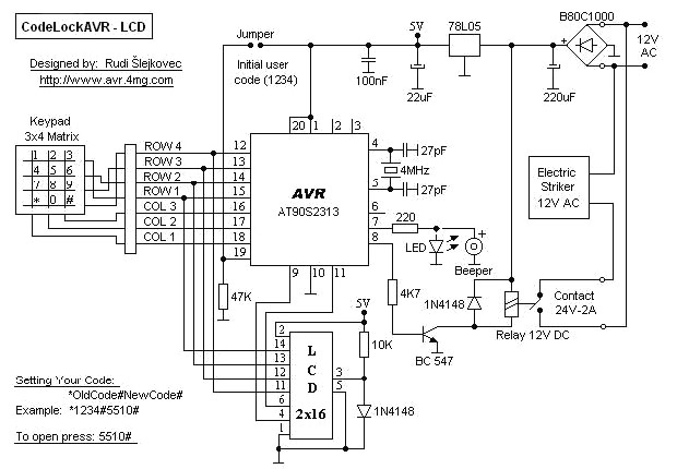
CodeLock electronic combination lock is realised with Atmel AVR microcontroller AT90S2313. Program in hex code is 2 kB long. User code is consisted of 1 to 4 digits.
If the code is entered in the correct sequence, then after 1 second the relay and the electric striker (in the door) switch on for 1 second and then switch off again.
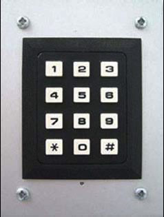
User code can be changed via 3x4 matrix keypad. Keypad can be bought at local electronic shop.
Initial user code (1234) is set up with a jumper. The jumper must be inserted before the voltage (12V) connection. The jumper must be removed after 2 beeps.
LCD display is an option!
Signaling
Each pressed key is immediately confirmed with one short beep. Two short beeps follow after entering the right user code. One long beep appears when entering the wrong user code. The keypad is blocked for 20 seconds for each incorrect action. User code is retained even in the event of a power failure.
You can use a LED diode instead of a Beeper. Look at the code lock electric circuit diagram.
The third row of the keypad (numbers 7, 8 and 9) can be unplugged. In that way you get 3x3 matrix keypad. If the additional row (the second one) of the keypad is also unplugged you get 3x2 matrix keypad. In that way you can use only: 1, 2, 3, *, 0 and # keys.
In short:
1. OPENING (For the first time): 1 2 3 4 #
The relay is being activated for 1 second.
2. WRITING YOUR CODE (For the first time): * 1 2 3 4 # 5 5 1 0 #
For opening the door press: 5 5 1 0 # (5 5 1 0 is your code)
The relay is being activated for 1 second.
3. CHANGING THE CODE: * OldCode # NewCode #
Example: * 5 5 1 0 # 6 6 1 0 #
Two short beeps indicate that new user code is written.
For opening the door press: 6 6 1 0 #
The relay is being activated for 1 second.
Circuit diagram